


Brand:GLSUN
Description:•Wide Wavelength Range •Low Crosstalk •High Stability, High Reliability •Modularized Design
Origin:China Guangxi
Model:SUN-OPS
MOQ:100Unit/Units
FOB:perUnit/Units1--5000USD
Port:Guangzhou/Shenzhen
Payment Terms:T/T
Supply Ablility:20000Unit/Units
Supply Time:Month
Delivery Time:2016-10-31
Packaging Details:by carton box
Product detail:
INTRODUCTION:
|
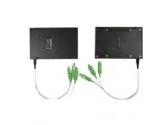
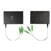
OLP Module(Multi Channel Optical Switch) - Features |
|
|
•Wide Wavelength Range
|
|
|
OLP Module(Multi Channel Optical Switch) - Working Theory |
|

|
|
| OLP Module(Multi Channel Optical Switch) - Specifications |


|
Parameters |
Unit |
OLP-1:1 |
OLP-1+1 |
OLP-1-1 |
|
Wavelength Range |
nm |
1260 ~ 1650 |
||
|
Test Wavelength |
nm |
1310 / 1550 |
||
|
Insertion Loss |
dB |
TX<1.2、RX<1.2 |
TX<4、RX<1.2 |
<1.2 |
|
Return Loss |
dB |
SM ≥ 45 |
||
|
Crosstalk |
dB |
SM ≥ 50 |
||
|
PDL |
dB |
≤ 0.20 |
||
|
WDL |
dB |
≤ 0.30 |
||
|
PD dark current |
nA |
<1 |
||
|
PD responsivity |
mA/W |
24 ~ 40 |
||
|
PD report accuracy |
dB |
±0.5 (at -50 to 23 dBm) |
||
|
Operating voltage |
V |
4.5 ~ 5.5 |
||
|
Operating current |
mA |
80 ~ 120 |
||
|
Operating Temperature |
℃ |
-5 ~ +60 |
||
|
Storage Temperature |
℃ |
-30 ~ +80 |
||
|
Dimension |
mm |
120×80×18 |
||
|
customization is available OLP Module(Multi Channel Optical Switch) - Pin Configurations OLP-1-1 |
|
Pin No. |
Signal Name |
I / O |
De |
|
|
1 |
2 |
NA |
|
Not applicable |
|
3 |
PD2- |
Output |
PD2 Cathode output |
|
|
4 |
PD2+ |
Output |
PD2 Analog output |
|
|
5 |
PD1- |
Output |
PD1 Cathode output |
|
|
6 |
PD1+ |
Output |
PD1 Analog output |
|
|
7 |
8 |
NA |
|
Not applicable |
|
9 |
10 |
NA |
|
Not applicable |
|
11 |
12 |
NA |
|
Not applicable |
|
13 |
14 |
NA |
|
Not applicable |
|
15 |
16 |
NA |
|
Not applicable |
|
17 |
18 |
NA |
|
Not applicable |
|
19 |
20 |
STA |
Output |
Switch status |
|
21 |
22 |
S1 |
Input |
Switch electrical drive |
|
23 |
24 |
S2 |
Input |
Switch electrical drive |
|
25 |
26 |
NA |
|
Not applicable |
|
27 |
28 |
D_+5VDC |
Power |
Digital power supply |
|
29 |
30 |
D_GND |
Power |
Digital ground |
|
31 |
32 |
A_GND |
Power |
Analog ground |
|
33 |
34 |
NA |
|
Not applicable |
|
35 |
NA |
|
Not applicable |
|
|
36 |
NA |
|
Not applicable |
|
|
37 |
NA |
|
Not applicable |
|
|
38 |
NA |
|
Not applicable |
|
|
39 |
40 |
NA |
|
Not applicable |
|
customization is available OLP-1+1 |
|
Pin No. |
Signal Name |
I / O |
De |
|
|
1 |
2 |
NA |
|
Not applicable |
|
3 |
PD2- |
Output |
PD2 Cathode output |
|
|
4 |
PD2+ |
Output |
PD2 Analog output |
|
|
5 |
PD1- |
Output |
PD1 Cathode output |
|
|
6 |
PD1+ |
Output |
PD1 Analog output |
|
|
7 |
8 |
NA |
|
Not applicable |
|
9 |
10 |
NA |
|
Not applicable |
|
11 |
12 |
NA |
|
Not applicable |
|
13 |
14 |
NA |
|
Not applicable |
|
15 |
16 |
NA |
|
Not applicable |
|
17 |
18 |
NA |
|
Not applicable |
|
19 |
20 |
STA |
Output |
Switch status |
|
21 |
22 |
S1 |
Input |
Switch electrical drive |
|
23 |
24 |
S2 |
Input |
Switch electrical drive |
|
25 |
26 |
NA |
|
Not applicable |
|
27 |
28 |
D_+5VDC |
Power |
Digital power supply |
|
29 |
30 |
D_GND |
Power |
Digital ground |
|
31 |
32 |
A_GND |
Power |
Analog ground |
|
33 |
34 |
NA |
|
Not applicable |
|
35 |
PD3- |
Output |
PD3 Cathode output |
|
|
36 |
PD3+ |
Output |
PD3 Analog output |
|
|
37 |
NA |
|
Not applicable |
|
|
38 |
NA |
|
Not applicable |
|
|
39 |
40 |
NA |
|
Not applicable |
|
customization is available OLP-1:1 |
|
Pin No. |
Signal Name |
I / O |
De |
|
|
1 |
2 |
NA |
|
Not applicable |
|
3 |
PD2- |
Output |
PD2 Cathode output |
|
|
4 |
PD2+ |
Output |
PD2 Analog output |
|
|
5 |
PD1- |
Output |
PD1 Cathode output |
|
|
6 |
PD1+ |
Output |
PD1 Analog output |
|
|
7 |
8 |
NA |
|
Not applicable |
|
9 |
10 |
NA |
|
Not applicable |
|
11 |
12 |
NA |
|
Not applicable |
|
13 |
14 |
NA |
|
Not applicable |
|
15 |
16 |
NA |
|
Not applicable |
|
17 |
18 |
NA |
|
Not applicable |
|
19 |
20 |
STA |
Output |
Switch status |
|
21 |
22 |
S1 |
Input |
Switch electrical drive |
|
23 |
24 |
S2 |
Input |
Switch electrical drive |
|
25 |
26 |
NA |
|
Not applicable |
|
27 |
28 |
D_+5VDC |
Power |
Digital power supply |
|
29 |
30 |
D_GND |
Power |
Digital ground |
|
31 |
32 |
A_GND |
Power |
Analog ground |
|
33 |
34 |
NA |
|
Not applicable |
|
35 |
PD3- |
Output |
PD3 Cathode output |
|
|
36 |
PD3+ |
Output |
PD3 Analog output |
|
|
37 |
PD4- |
Output |
PD4 Cathode output |
|
|
38 |
PD4+ |
Output |
PD4 Analog output |
|
|
39 |
40 |
NA |
|
Not applicable |
| customization is available
OLP Module(Multi Channel Optical Switch) - Dimension
|
|
|

|
OLP Module(Multi Channel Optical Switch)- Ordering Information: SUN-OPS-M-A-B-C-D-E-F-G |
|
A |
B |
C |
D |
E |
F |
G |
|
Type |
Fiber Type |
Test Wavelength |
Tube Type |
Fiber Length |
Connector |
Dimension |
|
Optical Line Protection System Module X: Others |
SM: SM, 9/125 |
1310: 1310nm |
90:900um |
05: 0.5m±5cm |
OO:None |
01: 120×80×18(ABS) |