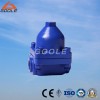
Pressure Rating: 1.6- 4.0Mpa
Specification: Screwed:DN15-50, Flanged:DN15-50
Material: cast steel
Standard flanges: DIN, ANSI, JIS; Standard screwed: NPT BSP
Performance / Advantages:
Adopt
There is condensation water in front of valve for forming water-seal, no fresh steam leakage.
Good exhaust, water hammer resistance and can be installed at any angle.
Application:
Mainly used for the steam pipe and overheating pipe, clear away the releasing temperature of condensation water automatically with
good saving energy.
Working Principle:
By the deformation of bi
Main Basis for Type Selection:
Condensation water loading (discharge)kg/h (selec the multiplying power 2-3 times).
Maximum working pressure Mpa
Operation pressure differential
Valve material and nominal pressure
Connection mode and dimension
Use and Maintenance:
Confirm the valve material, pressure and check if the maximum is suitable for operation condition.
Before installation, clean the pipeline and clear away sundries.
The installation position shall be closed to heating equipment as much as possible.
Install the minimum point of pipe horizontally and the direction of flow should be the same to the label of valve.
Install steam trap for each heating equipment in case cause influence each other.
under the safe operation of system, open the valve in front of the steam trap, make it rise up to normal station slowly.
Do time-based maintenance for the normal working of steam trap.
Performance Parameter/ Material List of Main Part:
|
Working Pressure Range |
0.05~1.6Mpa |
Allowable maximum temperature |
325 |
|
Valve body, valve cap |
WCB / 304 |
Hot sensitive element |
|
|
Valve seat |
2Cr13 / 304 |
Screen |
Stainless Steel |
 |
|
Product model |
DN |
Conjunction method |
Max.allowable temp. |
Material of valve body |
External dimension (mm) |
|||
|
L |
H1 |
H2 |
A |
|||||
|
BK TYPE |
15 |
Flange |
220 |
WCB |
150 |
100 |
22.0 |
85 |
|
20 |
Flange |
220 |
WCB |
150 |
100 |
22.0 |
85 |
|
|
25 |
Flange |
220 |
WCB |
160 |
100 |
22.0 |
85 |
|
|
32 |
Flange |
220 |
WCB |
200 |
140 |
39 |
- |
|
|
40 |
Flange |
220 |
WCB |
200 |
140 |
39 |
- |
|
|
50 |
Flange |
220 |
WCB |
230 |
140 |
39 |
- |
|
|
BK TYPE |
15 |
Internal thread |
220 |
WCB |
95 |
100 |
22.0 |
85 |
|
20 |
Internal thread |
220 |
WCB |
95 |
100 |
22.0 |
85 |
|
|
25 |
Internal thread |
220 |
WCB |
95 |
100 |
22.0 |
85 |
|
|
32 |
Internal thread |
220 |
WCB |
200 |
140 |
39 |
- |
|
|
40 |
Internal thread |
220 |
WCB |
200 |
140 |
39 |
- |
|
|
50 |
Internal thread |
220 |
WCB |
230 |
140 |
39 |
- |
|
|
BK TYPE |
15 |
Socket welded |
220 |
WCB |
95 |
100 |
22.0 |
85 |
|
20 |
Socket welded |
220 |
WCB |
95 |
100 |
22.0 |
85 |
|
|
25 |
Socket welded |
220 |
WCB |
95 |
100 |
22.0 |
85 |
|
|
32 |
Socket welded |
220 |
WCB |
200 |
140 |
39 |
- |
|
|
40 |
Socket welded |
220 |
WCB |
200 |
140 |
39 |
- |
|
|
50 |
Socket welded |
220 |
WCB |
230 |
140 |
39 |
- |
|
Advantages:
1. Bi
2. The valve is wide open when the steam trap is cold, giving good air venting capability and maximum condensate discharge capacity under 'start-up' conditions.
3. As condensate tends to drain freely from the outlet, this type of steam trap will not freeze up when working in an exposed position. The bodies of some bi
4. Bi
5. The bi
6. If the valve is on the downstream side of the seat, it will tend to resist reverse flow through the steam trap. However, if there is any possibility of reverse flow, a separate check valve should be fitted downstream of the trap.
7. As condensate is discharged at varying temperatures below saturation temperature and, provided water logging of the steam space can be tolerated, some of the enthalpy of saturated water can be transferred to the plant. This extracts the maximum energy from the condensate before it drains to waste, and explains why these traps are used on tracer lines where condensate is often dumped to waste.
8.Maintenance of this type of steam trap presents few problems, as the internals can be replaced without removing the trap body from the line.
The flash steam produced whenever condensate is discharged from a higher to a lower pressure will tend to cause an increase in back pressure in the condensate line. The cooling leg allows the condensate to cool down, producing less flash steam in the condensate line and thus helping to reduce the back pressure.


